smithtek-nodered-mako-decoder
v1.1.6
Published
Node that will decode Modbus data from the Mako PLC to useable json objects.
Downloads
10
Maintainers
Readme
Smithtek-nodered-mako-decoder
.png?raw=true)
Installation
Install the smithtek-node-red-mako-decoder using the NodeRED palette manager.
About
This node comes pre-installed on the Smithtek PassPort gateway. If you own a Mako V2 PLC, you can also utilize this node on other systems running Node-RED. To install, use the Palette Manager or execute the command:
npm install smithtek-node-red-mako-decoder
When used in conjunction with the Modbus contrib, this node parses polled Modbus data from the Mako PLC. Utilizing the V-NET software, you can create a data/register table in V-NET. The Decoder node is also capable of constructing an identical table, ensuring seamless and efficient decoding of PLC data.
Please note: This node is designed for reading data from the Mako and does not support writing values back to the PLC. To write values, you must use Modbus write nodes independently.
Declaration
This node is an adaptation of the previously published node-red-contrib-buffer-parser by Stephen McLaughlin. The Mako decoder can be used alongside the node-red-contrib-buffer-parser without any conflicts. To enhance usability, many features of the original node have been removed for a more hardware specific user experience.
V-NET Modbus
In V-NET you must build a Modbus data table, Input registers, holding registers, within these tables you add the registers data types. The following data types are what's available. The 32 bit data types are most significant word first. The conversion has already been don't in the Mako Decoder but you must select this function in V-NET next to each register in the properties.
- 16 bit integer
- 16 bit unsigned
- 32 bit integer
- 32 bit unsigned
- 32 bit float
- 8 * bool Unsigned binary encoder"
This item will split a 16 bit unsigned and output it in bool true/false. If using more than 1 bool see instructions below, decoders for digital inputs - Digital bits Unsigned binary encoder
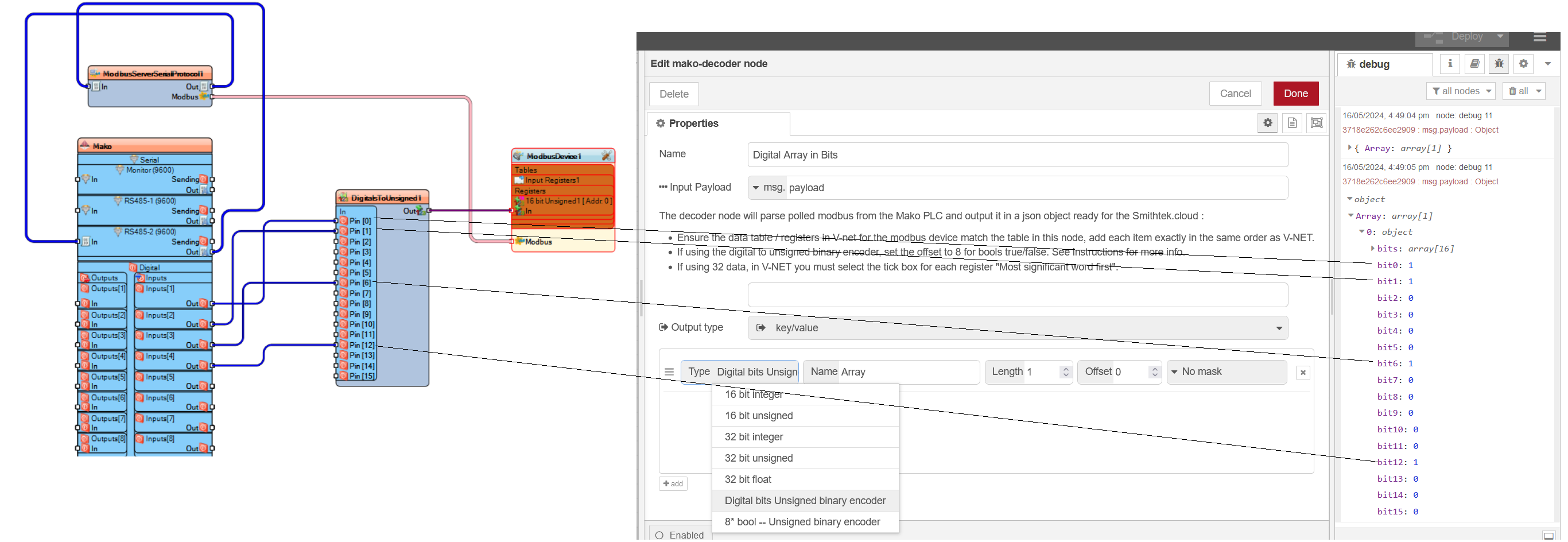
This item will split a 16 bit unsigned into separate bits nested in an array. Each bit has a json key "bit1":0 or 1
Matching data
The number 1 rule is to build your table in V-NET and then copy the exact same order of that table in the Mako decoder. Doing so will ensure the data is properly parsed for further use.

Physical wiring Modbus channels
The Modbus component in V-NET can be wired t0 1 or multiple interfaces:
- RS485-1
- RS485-2
- LoRa
- Modbus over TCP
- Serial Monitor External USB PassPort
A single interface can be used or all interfaces at the same time.
Building Modbus tables in V-NET

Mako Decoder - Summary of functionality
- Input data can come from any msg property (not limited to
msg.payload) - Output results can be multiple messages as
topicandpayload - Output results can be a single msg style output
- additionally, output results can be 1 of 4 styles...
- "value" : the parsed values are sent in an array
- "keyvalue" : the parsed values are sent in an object as key/value pairs
- "object" : the parsed values are sent as named objects with the value set
.valueand other contextual properties included (like the item - "array" : the parsed values are sent as objects in an array, with each object containing a
.valueproperty and other contextual properties included (like the item specification) - "buffer" : this mode simply returns a buffer (no item processing)
- Final values can be masked (e.g. a MASK of
0x7FFFcould be used to remove the MSB or0b1000000000000001to keep only MSB and LSB) - Final values can be have a Scale value or a simple Scale Equation
- e.g. Entering a Scale value of
0.01would turn9710into97.1 - e.g. Entering a Scale value of
10would turn4.2into42 - e.g. Entering a Scale Equation of
>> 4would bit shift the value0x0070to0x0007 - e.g. Entering a Scale Equation of
+ 42would add an offset of 42 to the final value - Supported Scaling Equations are...
<<e.g.<<2would left shift the parsed value 2 places>>e.g.>>2would right shift the parsed value 2 places>>>e.g.>>>2would zero-fill right shift the parsed value 2 places (returns a 32bit unsigned value)+e.g.+10would add 10 to the parsed value-e.g.-10would deduct 10 from the parsed value/e.g./10would divide the parsed value by 10*e.g.*10would multiply the parsed value by 10**e.g.**2would raise the parsed value to the power of 2^e.g.^0xf0would XOR the parsed value with 0xf0==e.g.==10would result intrueif the parsed value was equal to 10!=e.g.!=10would result infalseif the parsed value was equal to 10!!e.g.!!would result intrueif the parsed value was1(same as!!1 == true)>e.g.>10would result intrueif the parsed value was greater than 10<e.g.<10would result intrueif the parsed value was less than 10
- NOTE: the scale/equation is applied AFTER the mask
- e.g. Entering a Scale value of
Decoders for digital inputs
- 8 x bool Unsigned binary encoder.
- Digital bits Unsigned binary encoder.
To streamline this process, you can consolidate the digital I/O into an unsigned value. This allows the digital I/O to be read as input registers alongside other analog data, such as GPS coordinates, battery voltage, analog inputs, and counters. This approach not only simplifies your V-NET sketch but also reduces airtime when communicating over LoRa. Parsing Methods
There are two parsing methods available in the decoder: 8 x Bool Unsigned Binary Encoder: This method enables you to select bits individually from the message. You can assign each bit a JSON name (e.g., "digital input 1": true) and add it to the output payload as a Boolean value along with the other decoded data. Using this feature streamlines data management and reduces the complexity of your network communications
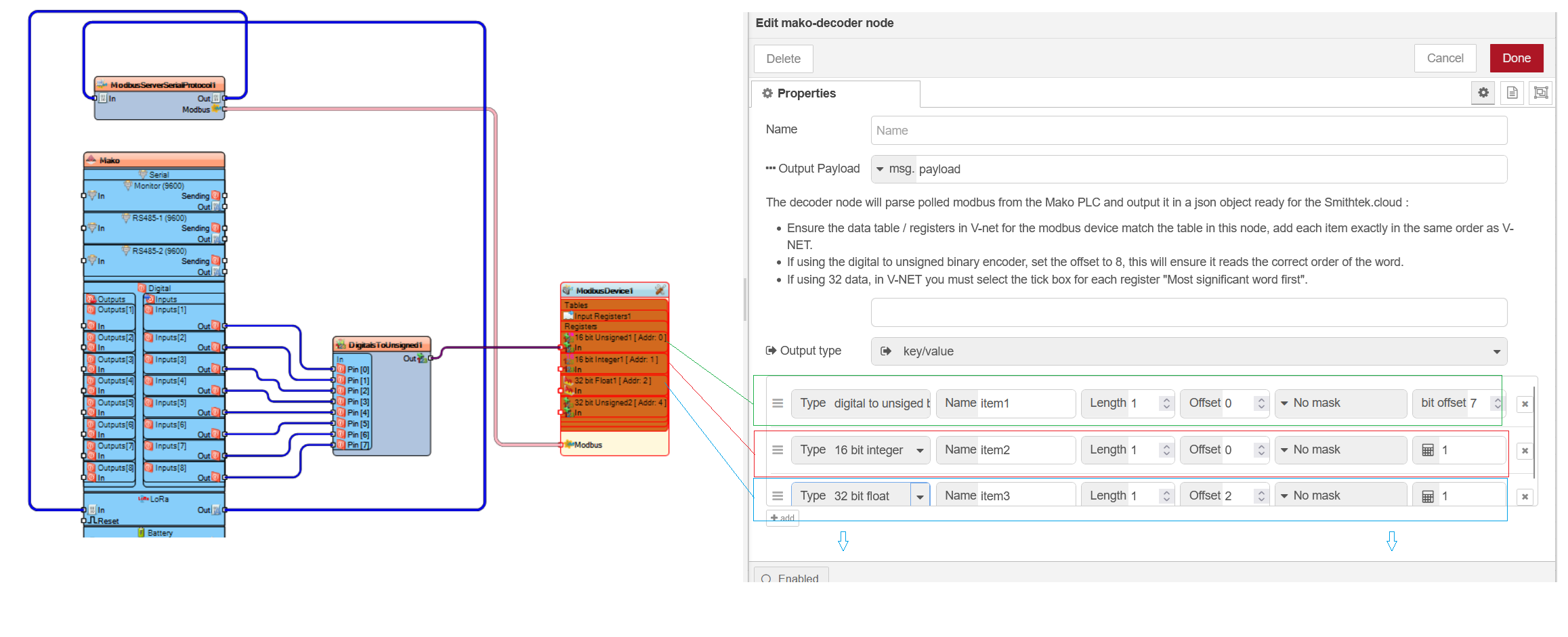
When using this method, ensure the item offset is on the correct word and then offset the first bit to 8. It will output the bool from the first PIN digital zero on the binary encoder component in V-NET. If you keep adding more items to the table it will automatically increment the bit offset. This feature has a maximum of 8 digital Ins.
The Digital bits Unsigned binary encoder is slightly different in that it can return the status of the complete 16 bit and output them in an json array with either a 1 or 0. The array will name the first bit "bit1" to "bit16" there is no configuring on this, just select the correct offset word and it will automatically output the array.
Digital bits Unsigned Binary encoder

8 x Bool Unsigned Binary Encoder

Mixed table of data types when using the 8 x Bool Unsigned Binary Encoder.

When constructing the decoding tables and integrating digital inputs, it is advisable to place them at the top of the table for easier management. As a precautionary measure and to future-proof your setup, consider adding two 8 x Bool Unsigned Binary Encoder instances at the beginning. Incrementing Offsets for Additional Data Types
When adding subsequent items, such as a float, you must adjust the offset appropriately to account for the entries that precede it. For instance, if you start with two instances of the 8 x Bool Unsigned Binary Encoder, each occupying an offset space, and then plan to add a float, you should increase the offset by 4. This means if the 8 x Bool Unsigned Binary Encoder entries are at the top, your float should start at an offset of +4.
This structured approach ensures that each data type is correctly aligned in your decoding table, preventing data overlap and ensuring accurate data retrieval.
License
Copyright (c) 2023 www.smithtek.com.au
Licensed under the terms of the GPLv3
Acknowledgements
Special thanks to
- Nick O'Leary and Dave Conway-Jones for their invaluable contributions to the Node-Red community.
- Stephen McLaughlin who's awesome hard work is the only reason we have this node :) Check his github here: https://github.com/Steve-Mcl
Contact: [email protected]
Website: www.smithtek.com.au
